System Diagramming Guide
Components, process, and examples of system diagramming tailored to techy folks and programmers
System diagramming helps us organize our thoughts and ideas about how a set of things are related to one another.
This thinking skill is widely applicable to almost all kinds of planning and systematic creative endeavors: logistical processes, work process layouts, trips with events, and many more.
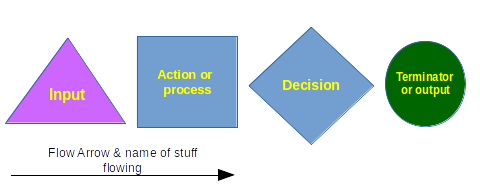
Diagram Components
The following graphic shows the set components we can use to make simply system diagrams. Note that we have inputs represented with triangles, processes as blue rectangles, decisions as blue diamons, and outputs with green circles. These are arbitrary shapes and could be replaced as needed. Arrows connect these components and the name of what is flowing from component to component is noted on the arrow itself.
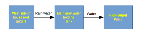
Basic flow relationships
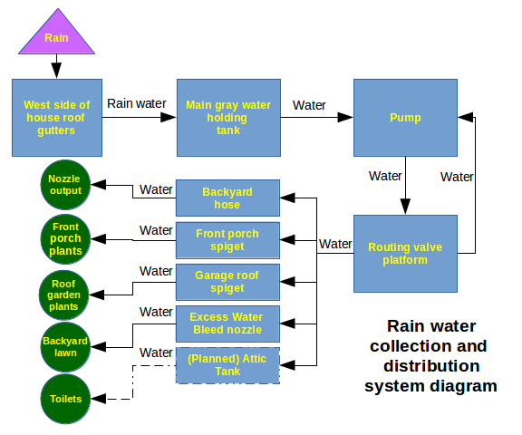
The simplest system diagram is made up of only processes and flows between them. This example flow diagram depicts the flow of water in Eric's rainwater collection system. Note that not all diagrams must have all components. The diagram should have enough components to illustrate enough of the system that we can learn what we need to from it.
Diagramming flows with decisions and outcomes
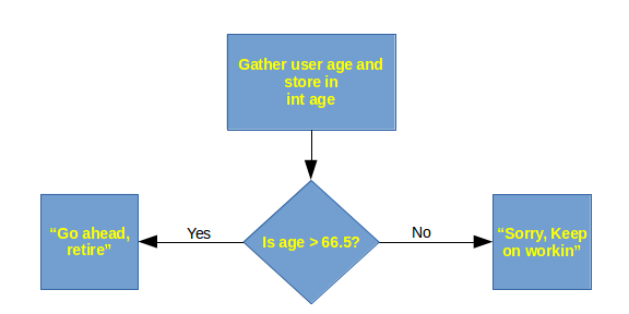
We can add our decision components, represented by a diamond, to map out more than one possible route of flow through the system. The decision or question goes in the diamond and the arrows flowing out of the diamond represent the possible outcomes of the decision.
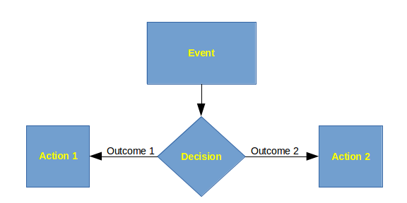
The above diagram shows the generic type of choice flow. The diagram below applies this method of diagramming to a system which determines whether the user can retire according to the Internal Revenue Service and the Socail Security Administration. Note that the actions the decisions lead to are both printouts to the screen for the user to read.
Diagramming more complicated systems
We can combine these ideas to model a more complicated system. The example below shows the complete flow of water through Eric's rainwater collection system. Notice that this diagram only depicts flows of water, not electricity. In other words, system diagrams are often partial system diagrams to avoid cluttering which can be distracting from the question at hand.
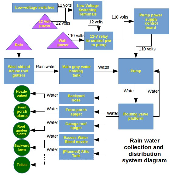
We can expand this diagram to include the electrical control system for the pump. Note that we have added two new inputs: high and low voltage power. The type of flow through the control system is not water but electricity of one of these two voltages. We can think of the control system as a sub-system of the larger rainwater machine.
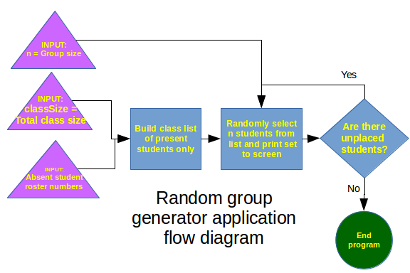
Modeling program flow
Computer folks use this method of organizing thinking because computers themselves were designed this way, resulting in useful diagrams for programming computers to do new tasks.
Draft and adjust your system diagram until it flows logically and arrives at a desired state or producing a desired outcome. Only then should you start implementing your system.
The following diagram depicts a high-level view of the random group generator program written in Java: